I'm sure a lot of you have seen this before and its a really powerful tool. I'm referring of course to the ability to have "Family Type" parameters in a family for nested sub components.
What does that mean?
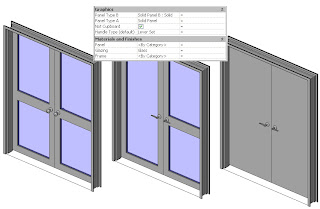
It means you have a single door where you can swap out the panel, or handles or frame. This avoids you having many different door families to achieve the same thing. It also means you don't have to load in 15 different families into your project, instead you may only need 2 or 3 and thus its better for file size.
Flexibility is a great thing.
So how do you make one of these parameters?
Well the key thing to having this work correctly is that all the sub-components that you wish to swap out must have the same insertion/origin point and be constrained by that point.
Begin with a template:
Start with a "non-hosted" generic model family template (remember you can always change the family category later).
Now we need to set the "defines origin" reference planes in the X, Y and Z planes.
My template for door panels is setup as follows:
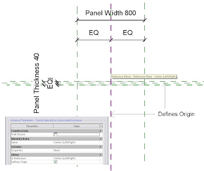
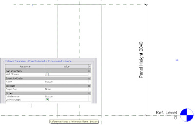
So my defining origin points are the Bottom Reference Plane (note I set it to be "Is Reference = Bottom), Centre Left/Right & Centre Front/Back.
Make note of this as when you load this panel into your project you need to define it by these points.
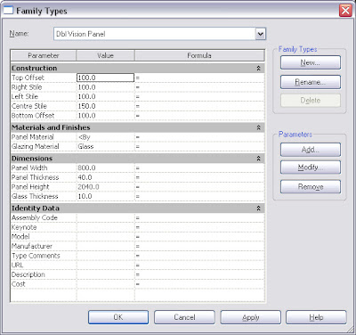
These are the parameters I include in the door. Note I have parameters to control vision panels if they exist. This way I have even more flexibility...
So once you've finished you need to load your panels into the host door family.
NOTE: This is personal preference, but I leave my door panels as generic models and set my door hardware to Furniture category.
DO NOT load lots and lots of door types into the one family. If you load too many your family will become too large and take ages every time you want to make a change to it. Load your standard door panels (most commonly used) only. I then have a subfolder that has an extensive library of door panels & hardware that I only load in on a per project basis...
Now we need to setup the host family.
Start with the Door Template. As a general rule I always delete the existing trim extrusions and remove their associated parameters. The other change I make is to the Width & Height parameters. In the template the height and width parameters are actually associated to the opening... I don't like this, I prefer to use the "Rough Height & Rough Width" parmeters for the opening sizes and then use the Width and Height Parameters for the panel sizes. So change this if you agree with my logic (just select the Width dimension and change it to Rough Width in your options bar pull down)
The next thing I'll do is load the panels that I want in the door family.
Upon doing this I immediately link through the parameters for every door type I loaded...

 This is the labourious part. Go to each type you loaded in the project browser, go to the element properties for each one, then link through all the parameters by clicking the "link" column for each parameter. For the first one you will need to use "Add Parameter..." for the ones that don't exist yet. Then after this you can just pick them. Note I link Panel Width & Panel Height to Width & Height respectively. (note for double doors I don't do this because I have extra parameters for each door panel, left/right).
I then go to plan view and place one of the door panels randomly. I then constrain its left/right location using its centre left/right origin point (use the align tool and then lock it). I then constrain its front back location using its Centre front/Back origin point.
I generally have an undercut parameter so to constrain the Door in the Z axis I go to element properties and in the instance parameters I'll link the level offset parameter to my undercut parameter...
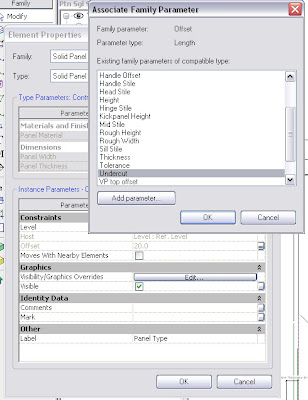
So we've now constrained the panel in the X, Y & Z axes which was the insertion point of the panel.
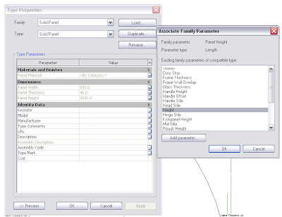
Now we need to add the Family Type parameter to enable us to swap out the panel for the other loaded panels...
Select the panel you placed. Look at your options bar
 You see there is drop down called label and its currently set to "None". Select "Add Parameter", give it a name and your done.
If you load this door into a project you now have a parameter that enables you to swap out the panels as needed.
Now this quick tutorial didn't really go into the depth of creating a door it was more to concentrate on the parts that are required to successfully create a working "Family Type" parameter.
I hope someone finds this useful.
Post if you have queries, as I'll add more detailed info if it proves people still have trouble.
Cheers.
32 comments:
Thanks Mr. Spot!!
Although I use Revit structure and not Revit Building, I enjoy reading about the many different things you can do in Revit. I personally am just starting to push across that uncomfortable line of editing and creating custom families with parameters. I appreciate the time you put into your tutorials and have found them quite helpful. Do you have any advice for learning how to create and get comfortable with custom families? Thanks
JB
Your welcome.
Obviously every family creation is different but the standard rules exist across all of them.
I'll always sit down and sketch out a plan of what I'm trying to achieve first.
Work out where you want the insertion point to be...
Work out what parameters you are going to need and whether you are going to need to schedule any of them...
Are nested families going to help? Nested families mean constraints are easier to manage.
Work out what references you need for dimensioning in projects and place reference planes where these are. Then set all other reference planes to not a reference.
Place your reference planes first and parameters before placing geometry.
Flex... to ensure everything works - ensure to flex the host.
When drawing in the sketches for the geometry don't assume the locks that come up are associating to what you want them to. Use the align tool to ensure the sketch lines are correctly locked to reference planes.
Fill out your family types.
Create a type catalogue for families with lots of parameters and sizes rather then setting them all up in the family. Check the tutorials on how to do this.
Don't forget to add parameters for materials.
Don't forget that you can make use of visibility parameters on/off.
This is a good basis.
The more you try the more you learn...
Can you please add a menu for your archive?
It's impossible to browse your old posts for all your tutorials without searching.
Many Thanks.
That was strange. I had already incorporated the archive but wasn't displaying.
Should be working now...
is there any way to get a PDF of this. when printed the dialog boxes are not that clear. my email is coreed@hdo.com
thanx
Sorry Coreed,
Have to leave some advantages for my own company :)
You'd have to come work for us if you want a PDF :P
Cheers.
chris, i think you are your company's best advantage. i'm just a humble servant of Revit Guru's like you, trying to learn as much as i can. but i compeletely understand your point.
coreed,aia
Chris,
I've got my doors very similar to yours, though i'm having one problem, i can't schedule the panel type. Is there a way to do this so that each panel woudl be schedule friendly?
Thanks
Yes there is :)
You need to go into you panel families, go to family category & parameters in settings and tick "shared".
This enables them to be scheduled. Then in your project just create a schedule for whatever category you've set your door panel and filter out irrelevant stuff as needed.
HTH.
also meant to say congrats on the wedding, i'm doing the same in 8 days!
however, my door panels won't allow me to link their labels to the shared parameter labels in my door family. my door frame works perfectly, but i can't get the door panels to play nicely.
I have them brought in as components, they can be placed, but that's about it. Any idea on what i'm doing wrong, been running in circles on this one today.
Many thanks for the pointer of making them shared.
Would need to look at the files mate. Very difficult to diagnose on that...
Could be an origin location issue, what errors are you getting?
i don't get any error, though it's when i tick the "shared" parameter as suggested that i can no longer link my labels of that panel to my shared parameters.
i have a feeling i might be missing a step somewhere when making my panels...
thanks for the help.
Setup your nested subcomponent parameters as instance parameters in that family.
You can't have type parameters linked when the subcomponent is set to be shared...
They can be type parameters in the host family though.
So basically you are linking instance parameters to a type parameter in the host.
HTH.
Chris,
Once you place a door with multiple types into your project as you have outlined are you then controlling which panel is being used in each door location as an instance parameter and changing it per door?
Great post, and thanks in advance for your feedback.
In my particular case I have the panels as a type parameter and the hardware as instance based.
But you can set it up to be instance based if you prefer. Just remember the nested family has to be a type parameter and then link the type parameter to an instance parameter.
HTH.
Chris,
Thanks so much for the feedback, things seem to be working now. I was however wondering that in the first screen capture you have you show a door with glass in it. Are those sizes of the side a top rails set only in the Generic Door Panel or are you mapping those back to the final door assembly so they can be controlled once in the project? If you are mapping those does there need to be a series of identical reference planes in the completed door model to achieve this?
Thanks again for this great post.
Those can be controlled in the project also. As can the handle location/height. I have parameters for Glazing head offset, glazing handle offset, glazing hinge offset, glazing sill offset...
The only reference planes you need in the host family are those to constrain the positions of the loaded elements and any modelled geometry directly within that family. There is no need to add reference planes for the glazing because it is already constrain in the panel family.
Cheers.
Got it, thanks again for the great insight. As you can see I am on a mission here as I start to set up standards for our office. One last question. In you tutorial you say "I then constrain its (the panel)left/right location using its center left/right origin point (use the align tool and then lock it)" When you have a double door scenario how are you achieving this? In my family I created a Panel left and Panel right parameter to control the width on either side of the center left/right origin. Then I tried to lock my panel family and think this is where I messed up. I was not paying attention to the origin points I created per your instructions for the panel family. Should I have a parameter tied to an EQ/EQ dimension for that center left/right origin of the panel family?
I just got home and might have to try that in the morning but thought I would throw that out there to see if I was on the right track....
I have a parameter for panel A width and panel B width.
I place a reference plane at the central point of each panel and constrain it appropriately using EQ constraints.
Give it a go, just get your reference planes working first before you constrain the panel to it.
HTH.
Thanks for the clarification, that's exactly what I was referring to. I had the reference planes flexing correctly but I was locking the geometry to the wrong items, which was creating the error message. I think I'll be able to sleep easy tonight and re-attack the doors in the morning.
Thanks again, I will let you know how it goes.
I think I got it...Once I got passed the hurdle of understanding which reference planes were the origins and making sure I have those addressed correctly in the family where I was inserting the panels things seemed to go well.
Thanks again for your feedback and great posts on your blog.
As per your guide lines I have made a window family { a frame, a shutter & a grill). I added parameters for nesting shutter & grill to window frame, but getting problem to nest them. How can I attach the rfa files to this post so that you may check them? I have already posted this in AUGI " To many constrain...."
Could you do an example with an annotation? For instance I'm trying to insert a symbol for an outlet and I want to have different symbols(types) for single outlet vs. duplex outlet and so on.
How many different types? If there is only 2, duplex and single then you'd be better off using visibility parameters. Just add a yes/no parameter to the visibility of each element and then add a formula such as:
Vis1=Not(Vis2)
This way you'll just end up with a toggle button that flicks between the two.
I have 8 different types of outlet symbols that I want to just be able to switch the outlet type and have the new symbol show up. So the difference between my types is primarily the graphical representation and I don't know how to change how it looks and save that as a type and then change how it looks agian and make that a new type.
Have a go at this, and if you still have trouble I'll create a new post for annotations. There are 2 ways to do it. 1 is more user friendly (this one) and the other is leaner on file size.
Create your various symbols as seperate families (always purge all unwanted information out of the nested families to minimise file size).
Load these families into your host outlet family.
Insert one of them.
Select it and in your options bar choose "add parameter".
Name it and group appropriately (leave as a type parameter).
Then go to "Category & Parameters".
You can now create your new types and select different annotation families in their pull down as needed.
HTH.
Thanks for your help. I think I got it :)
Do you know how to put a grip on a symbol tag? For instance if you have a dimension you can put your mouse over the text and it gives you the option to drag the text and move it so that it's not overlaping anything else. I want to be able to this with a light fixture, for instance, with its fixture tag. Sometimes the text might overlap another symbol that is near by like an occupancy sensor. Your help would be appreciated.
Holly
do you have your frames set up like this too? If so, what do you do about frames with sidelites, and how are those created? (i assume generic wall based families?)
Personally, I have different families for "Timber Frame" & "Steel/Aluminium Frame" Doors. These are tied to reporting parameters that allow the frame to adjust based upon the wall thickness.
We don't do a lot of residential and have never really had the need to create doors with sidelites/hilites. If I did I'd probably place the sidelites and hi-lites as separate elements (unless I did a lot of them, in which case I might nest them all together). As to what category to use it depends on how you want the sidelites/hi-lites to schedule...
Do you want them to schedule separate as windows? Or are you happy to just schedule them as part of the door?
Lots of questions as always and the answers really define how best to tackle something like this...
I was wondering if anyone has ever run into a problem when using the "Family Type" Parameter where the object disappears when swapping between different models. In my case I'm using a door family with nested panels, and when i switch the panels sometimes the panels disappear completely from the model, (3d, elevations, plan, etc.) It doesn't happen all the time, and it doesn't always happen to the same panels. It seems to be most problematic in Revit 2011, and when i load it into Revit 2012 it seems to work better. The models were all created in Revit 2011.
Thank you. I'm just getting into nested families. This is so helpful.
Post a Comment