1. How can I override the dimension text? (You can now do so in R2009+)
Simple answer, you can’t. Workarounds are best explained here http://revitoped.blogspot.com/2005/11/de-value-engineering-dimensions.html
2. I created some levels but there aren’t any plans associated with them, can I add them?
Of course: Go to View->New->Floor Plan… and simple select the views you wish to create plans for. The standard windows ctrl and shift click selections apply here. The same principle applies for ceiling plans.
3. I can’t see some of my levels in one of my elevations/sections?
All levels/grids/sections (referred to as datums) have 3D and 2D extents. If the 3D extents of that level don’t cross the 3D extents of the section or the elevation they will not show. Therefore, to make them show you need to adjust them in an elevation/section so they do intersect. When you select a datum an indicator displays showing whether the datum is currently set to 3D or 2D extents. This is a toggle, click on it to toggle its value. If you right click on the datum in a view it does display in and select maximise 3D extents it will expand the extents to the full boundaries of your model, which should hopefully make it show up in your appropriate view.
If they don’t show in any views, you’ll need to create a scope box. Under your drafting tab is a tool called scope box, use it to draw a 3D box completely around the extents of your model. Now in elevation add another level (this will be temporary), right click and choose “select all instances” go to the properties and there is a category called extents. Where it says none, click and choose your scope box for the drop down menu. Then click okay and your levels should now appear as there extents have been adjusted to that of the scope box. You may delete the scope box now if you have no further need for it.
4. How do I place a door in a curtain wall?
Curtain walls do not behave the same as normal walls and doors are not placed in the same manner. There are two options for placing a door in curtain wall.
In your modelling tab, place curtain grids to break up the panel to the size you’d like to make your door. Switch to a 3D view, hover over the edge of your curtain wall panel where you’d like to place the door. Now use the
The other option is to change the panel to a wall type. You may have noticed in the previous method you could pick from available wall types. If you change the panel to a wall you are then able to place doors as you would a normal wall. You could even make the door take up the full extents of the wall so it wouldn’t matter what wall type you actually used. There are issues currently with this method and schedule to and from room information of doors placed this way.
5. Can Revit create linetypes with text along the line or symbols to represent stormwater or various other services?
The short answer is no. You can create a line based detail component, but the text symbols would need to be a nested symbol family. I've created one which enables me to set the value for the text to anything I want as a Type parameter. You can't currently do this for a curved line though...
6. How do I change the swing angle in plan of my doors?
This feature is only available if the door has been created with an instance parameter for the adjustable swing. This is best explained in the in-built Revit Tutorials.
7. How do I create my own hatch patterns?
You can either learn the appropriate code to edit the pat files directly using a text editor such as notepad or utilise a program such as Hatchkit. http://www.hatchkit.com/
8. How do I change a model pattern to a drafting pattern or vice versa?
Edit the PAT file using notepad and add or change the following values:
;%TYPE=MODEL for model or
;%TYPE=DRAFTING for drafting.
You can also set the units with the following operator:
;%UNITS=MM to set to millimetres…
9. How do I change the elevation symbols to match my section markers? (You can now do so in R2011+)
This isn’t possible. Elevation tags are system families and can only be modified using the settings in the elevation tag properties… This is a long standing wishlist item.
My typically workaround (for times where its absolutely necessary that the elevations look a certain way) is to create a new section type called "Building Elevations" Then I'll give the section a head with no tail, then drag the section cut line in plan to be short enough that its not visible. Refer to the tutorial...
10. I have a window above the cut plane that I need to display but I can’t change the cut plane without effecting everything else?
Create a plan region. A plan region allows you to draw a boundary and adjust the view range settings for that area independent of the rest of the view. The great thing about 2008 is no longer do you have to search for plan regions by hovering around your model, they now display a boundary in plan that doesn't print.
11. How do I apply different materials to individual wall faces or similar without having to make a new type?
Use the paint brush tool from the tool bar. Select the appropriate material then pick the face you’d wish to paint; to reset the material back to its original settings, paint it with the by category
12. How do I attach a wall to the underside of a stair/ramp?
Refer to this tutorial. http://www.revitcity.com/tutorials/stair-wall_trimming/. Hopefully this process will become more automated with future releases. Another way is to use the ramp tool, or to select the wall and split it at each tread...
13. I placed a beam but I can’t get it to show in section/elevation (it only shows as a line)?
Change the detail level of the view from coarse to medium or fine.
14. How do I create a slanted/sloped column? (You can now do so in R2010+)
In 2010 onwards simply use a structural column and set the angle in its instance properties. Otherwise, you need to create a column with adjustable parameters for the angle. Refer to this thread: http://www.revitcity.com/forums.php?action=viewthread&thread_id=592#2062
15. The floor hatch pattern is showing through my plumbing fixtures/furniture in my plans, how do i stop this?
This is caused by a setting in each of the families themselves. If you edit the family, switch to a 3D view and select all the 3D geometry, then hit the visibility button on your top tool bar. You'll notice that its turned off in plan, you can turn it back on here and reload if you like.
If the 3D geometry is an imported dwg, there maybe excessive 3D linework which you don't want to display in plan. In this case you'll need to create a masking region (2008) to represent the element in plan and line up with the 3D geometry - you'll also most likely need to do this in front and side elevations as well.
16. How do I create a canted/slanted/tilted/angled wall?
You need to create a mass to give you the correct angled surface of which to place your slanted wall. Masses are used as an invisible framework to control entire building layouts or complex geometry such as this.
Once you have created your mass, either by solid extrusion or a blend (depending on the slanted walls complexity), you can use the Wall->By Face option or Curtain System by face for curtain walls. Just select the type of wall you'd like to place then pick the surface.
Then its just a matter of turning your mass visibility off...
You can use geometry created in other programs as a mass (such as sketch up or Rhino)
17. How do i save back to a previous version of Revit?
This is not possible. Revit is bought on a subscription basis only, so there is never a reason not to have the latest version installed. This way the Revit support team can concentrate on supporting one version of Revit rather than having to maintain superseded releases.
18. Red Question marks are showing up in my titleblock and i can't type in the appropriate values?
This means that there are shared parameters in your titleblock which are yet to be loaded into your project. If you are not aware of what shared parameters file they are located in and the parameters names, edit the titleblock, select the label and edit the parameter to find out where its located first.
Then in your project goto Setting-->Project Parameters-->Add-->select shared parameter and navigate and find the parameter you wish to add-->Select what category of families you wish the parameter to apply to, in this case either project info or drawings sheets (generally drawing sheets)-->Then select whether its an instance parameter or a type parameter-->Hit Okay and repeat for any additional parameters.
19. When rendering there is this plane showing through my building that i can't get rid of?
This is most likely a ground plane. Many people forget that the ground plane is set in TWO locations and must be off in both of them.
These locations are:
Settings-->Render Scene-->Environment-->Advanced... Ground plane
and
Settings-->Sun & Shadow Settings-->Ground Plane at level.
Turning this off in both this locations should resolve the issue.
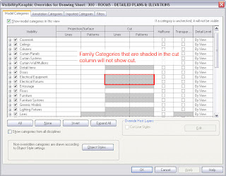
20. Why won't my family show cut by a section?
If you look in your Visibility Settings (shortcut - VG or VV) you'll see in the Cut column some cells are greyed out. This particular family categories do not show cut by a section. Instead if a family is cut of this category the entire family displays. This was obviously implementing for items such as a couch where you don't want to see if being cut in a section. Personally I think all families should have the option in their settings as to whether they are cut or not rather than not giving us a choice.
To resolve this go to Settings-->Family Category & Parameters and change your family to a category that will show cut.
10 comments:
Hey Chris (Mr Spot). Great to see you into blogs, welcome.
The Revit Family Man
Shaun van Rooyen
Thank you for your page!
I really appreciate you sharing these solutions to common problems.
Thank you!
Thanks everyone for your feedback and I'm sure to reply more often to these comments now i've discovered the moderate comments section... ;)
Turned it one when i started getting adds posted then forgot to actual do the moderation.
Cheers!
Aewsome post! Helped with a lot of my Revit issues.
Thanks for #3 about the levels! was very frustrating problem, and a nice easy fix!
the slanted wall solution doesn't work for curtain walls or storefronts.
For curtain walls you need to use the curtain system by face instead. You can only using basic walls using the wall by face option...
HTH.
Thanks!Thanks!And one more time thanks!!!! Due to your blog I succeeded to insert a door into a curtain wall!
Anna
awesome, I was having trouble with number 20. Grrr Revit, what a bizarre thing to think of
When I am working with a 3D model the windows and doors on the sides and on the back side of the house are seen as shadows on the 3D view of the building . How can I get rid of this .
Post a Comment